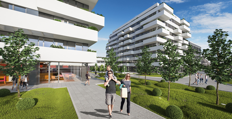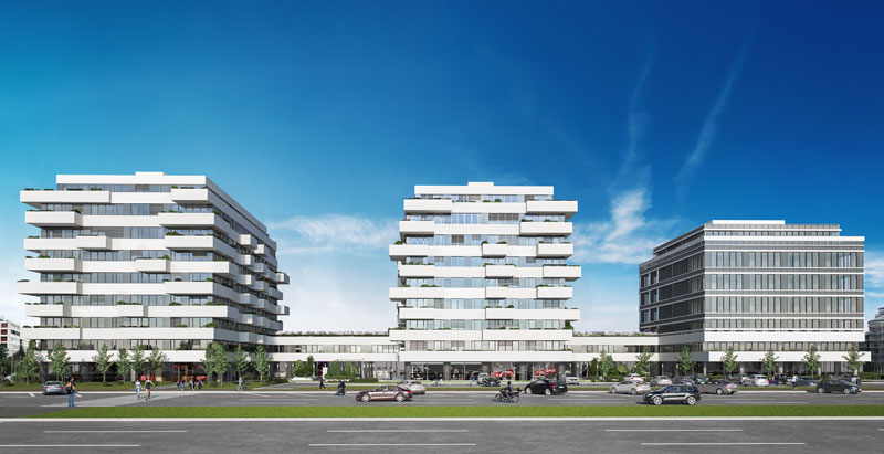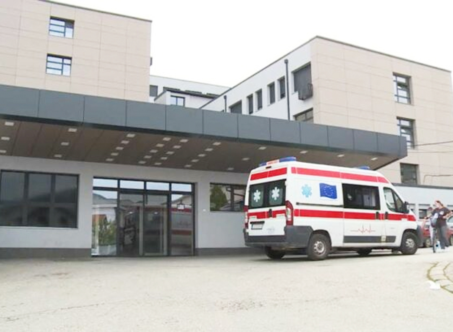

Implementation of technical systems - Block 32
1. AUTOMATIC FIRE ALARM SYSTEM
The fire alarm system provides timely signaling of the fire, the place of origin of the fire, as well as alerting the staff on duty and people present in the building that a fire has occurred. Fire signaling was carried out via alarm sirens and on the central device, and an automatic telephone alarm notification was also provided.
In order to achieve the aforementioned functions, the fire alarm system consists of:
- of analog-addressable fire alarm control panels
- parallel board
- automatic and manual fire detectors
- signaling elements (sirens, parallel indicators, telephone pager)
- executive I/O modules
- cable installations.
The planned system provides information to the central office from each detector and fire alarm with an individual address. In this way, each room has its own address (zone) on the switchboard, which enables quick definition of the place where the fire broke out.
At the level of the complex, a distributed fire alarm system with 2 addressable fire alarm centers interconnected in a communication ring is planned. In the porter's room on the ground floor, there is a parallel panel for monitoring the system. Local fire signaling should be realized through alarm sound and light signaling.
Certain information important for the safety of the facility is fed to the automatic fire alarm system. This is realized by input (acquisition) modules on the detector loop. The status signals of the state of certain technical systems are fed to them (eg the operation of the extinguishing system and others). These signals are forwarded to the fire control center, which treats them as a warning or useful information for taking further steps regarding the safety of the building. The extinguishing control center transmits information about the pre-alarm (detection zone operation) in the specified manner. Also, in the same way, the extinguishing control center forwards the extinguishing block, extinguishing activation and error signal information from each extinguishing module.
In order to power the alarm lines that are far away from the fire alarm control center, additional power supply units with spare accumulator batteries are provided, which are distributed throughout the building in such a way as to enable the power supply of all the intended alarm lines. All cabinets with power supply units are properly grounded with a 16mm copper braid2.
Given that there is a 24-hour on-call service in the building, for the sake of timely notification of the emergency, i.e. fire service, there is no need to connect a telephone answering machine to the system.
Automatic fire detectors are installed in all hospital rooms, medical staff rooms, doctor's rooms, offices, hospital blocks, common rooms, technical rooms and all other rooms where there is a fire risk.
Manual fire detectors are placed on the evacuation routes along the corridors, staircases, at the entrance to the building.
For the basic type of detector of the fire alarm system, an optical smoke detector was adopted, because it detects the occurrence of fire at an early stage of its development.
Appropriate relay modules are provided for the implementation of executive functions. Internal alarming in the facility is provided by alarm sirens.
2. CARBON MONOXIDE DETECTION SYSTEM
The gas detection system is designed in accordance with current fire regulations. Forwarding of alarm signals from the gas detection system to the central fire alarm system is also foreseen. This connection is realized via input modules. The control center of the automatic fire alarm system will act on executive functions.
This system serves to detect an increased concentration of carbon monoxide and consists of:
- central device with the appropriate number of zones
- CO gas detectors
- single-sided and double-sided warning panels
- alarm sirens with flashing lights
- cable installations.
3. VIDEO SECURITY SYSTEM (CCTV)
In accordance with the purpose of the facility and the requirements of the investor, a modern IP video surveillance system with the most modern high-resolution cameras, minimum 2MP (1920×1080), is planned, which will ensure monitoring of the entire complex of the facility with cameras selected and positioned so that the facade of the facility and the environment of the complex are covered by as deep as possible. This involves monitoring all entrances to buildings, corridors, vehicular and pedestrian entrances to the complex, as well as common areas and special purpose rooms within the building. All cameras are ONVIF compatible, have at least two types of image compression H264 (or H265) and MJPEG, the possibility of simultaneous sending at least two stream-a, data encryption, day/night function, WDR, backlight elimination, to have built-in IC diodes and a slot for an SD card. The technical solution ensures local storage of the recorded material on the central NVR/Sotrage device for a minimum duration of 30 days, in accordance with the law on private security. Supervision and control over the video surveillance system will be carried out by trained security personnel with the appropriate license of the MUP.
4. ANNOUNCEMENT AND ANNOUNCEMENT SYSTEM
The project envisages a 100W sound and notification system that should cover all common areas of the facility, corridors, nurse's and doctor's rooms, rest rooms, and patient rooms. Built-in or surface-mounted speakers are provided in all parts of the facility. A combined analog and IP system was installed for voice notification and broadcasting of sound recordings.
The installation of a public sound system allows the broadcasting of radio programs and local audio programs via MP3 players, as well as the possibility of broadcasting various notifications to staff via microphone consoles or automatic notifications in case of danger.
The system is divided into several zones in accordance with the organization of the facility.
5. ACCESS CONTROL SYSTEM
The access control system is intended for controlling the movement of employees/visitors and access to certain premises/business zones. It is also intended to protect the object from unauthorized entry into protected premises. The system is designed to increase security by defining access permissions for each user based on specific areas in the facility and time. The system keeps and maintains records of these events.
The access control system has the ability to define both spatial and temporal zones, in an arbitrary way and without restrictions, in accordance with the wishes of the user. The same software has the ability to record working hours, but the validators of working time records are special. The system allows the creation of multiple hierarchical levels of user accounts with different software access rights, and complete user control over the system and card programming will only be available to personnel with software-assigned rights.
6. VIDEO INTERPHONE SYSTEM
At certain locations / entrances where the need arises, a modern IP video intercom system is provided. Video intercoms cover all pedestrian and vehicular entrances to the complex. The communication center is the security desk where the IP video intercom monitor was installed.
7. ANTI-BURGLARY ALARM SYSTEM
In order to protect the building from raids and break-ins, the project foresees a burglary alarm system inside important buildings within the complex. Anti-burglary protection should ensure the detection and signaling of any attempt at unauthorized entry into the building when no personnel are present. For burglary detection, a PIR or dual PIR/MT presence detector, glass break detectors and magnetic contacts are used to protect all rooms around the perimeter of the building on those floors that can be accessed from the outside. The system consists of one or more anti-burglary control panels depending on the configuration of the buildings and is divided into several anti-burglary sectors/partitions and is zoned according to the architecture of the buildings. Each anti-burglary sector/partition has the possibility of separate arming and disarming from keyboards/coders positioned at the entrances to the sectors. The entire system will be monitored by security personnel.
8. STRUCTURAL CABLE SYSTEM
The network was implemented as a structural cable system in accordance with ISO/IEC 11801 and EN 50173 standards, as well as based on the recommendations of the leading equipment manufacturers in the field. The system will enable data transmission within different architectures of computer networks (Fast/Gigabit Ethernet, ATM, etc.)
Two independent LAN networks are provided in the associated facility:
- DATA (CORPORATE) LAN, i.e. electronic network for data transmission, realization of voice communication (VoIP) and distribution of Internet signals.
- SECURITY LAN, i.e. electronic network for transmitting signals of security and safety systems such as: video surveillance, access control, fire alarm, gas detection....
It is intended that each LAN interface be of category 6a (cables Cat.6a, connectors Cat.6a) which ensures a data flow of up to 10Gbit/sec. The structural cable network consists of: common tracer equipment (lines, pipes, hoses, penetrations, vertical...), common optical trunk cable, but with the use of separate optical fibers for each network (DATA and SECURITY) and common floor racks in the server room and technical support room, but separate and completely independent copper installation, separate passive connection equipment (optical and copper patch panels), separate access switch- in common floor closets. The main concentration of the network is the server room on the first floor of the building. In the server room, one standing rack cabinet 42H is provided, and another rack cabinet, also 42U, is provided in office 30 on the building's floor.


